Build Backend Business Logic with Visual Flows
Use the Logic Flow Builder to define what a request does after it receives input and before it returns a response. A flow combines request fields, action nodes, branches, outputs, and error paths on one canvas. If you are building the reusable actions that appear here, start with Logic Node Overview.
Create and configure the request first. Then open its handler from the request node or from the Handler control in the right sidebar.
Logic Flow Basics
Every request has its own root logic flow. The editor displays:
- Inputs on the left, including body inputs, path variables, query parameters, and headers.
- Action nodes in the middle, where data is queried, transformed, checked, logged, or secured.
- Outputs on the right, including successful and error responses from the request.
- Edges between compatible ports, which show how values move through the flow.
To build a basic flow:
- Open a request's handler.
- Confirm the input and output groups match the request contract.
- Drag an action node from Logic Nodes in the right sidebar.
- Select its variant when the node offers more than one behavior.
- Configure the node and connect the required values.
- Connect its result to another action or to a request output.
- Resolve every error or warning before leaving the flow.
Use the interactive demo below as the visual reference for this workflow. It shows building a complete logic flow, adding request inputs and outputs, placing an action node, and connecting compatible input and output handles.
The top breadcrumb shows the request and any nested branch currently open. Use Back to return one level, or select an earlier breadcrumb to leave deeper nested logic. The copy action exports the complete request and flow structure as JSON for review or support.
Action Nodes
An action node performs one focused operation. Built-in nodes include Query, Condition, Loop, Variable, Log, Token Management, and Password Management. Reusable custom nodes from your workspace can appear in the same library after their visual structure and code template are published.
Drag a node into the active logic flow, then work from top to bottom: choose its behavior, connect or create inputs, complete its configuration, inspect branch flows, and route its outputs and errors. For custom nodes, those visible parts come from the node's variants, config lines, fields, and element packs.
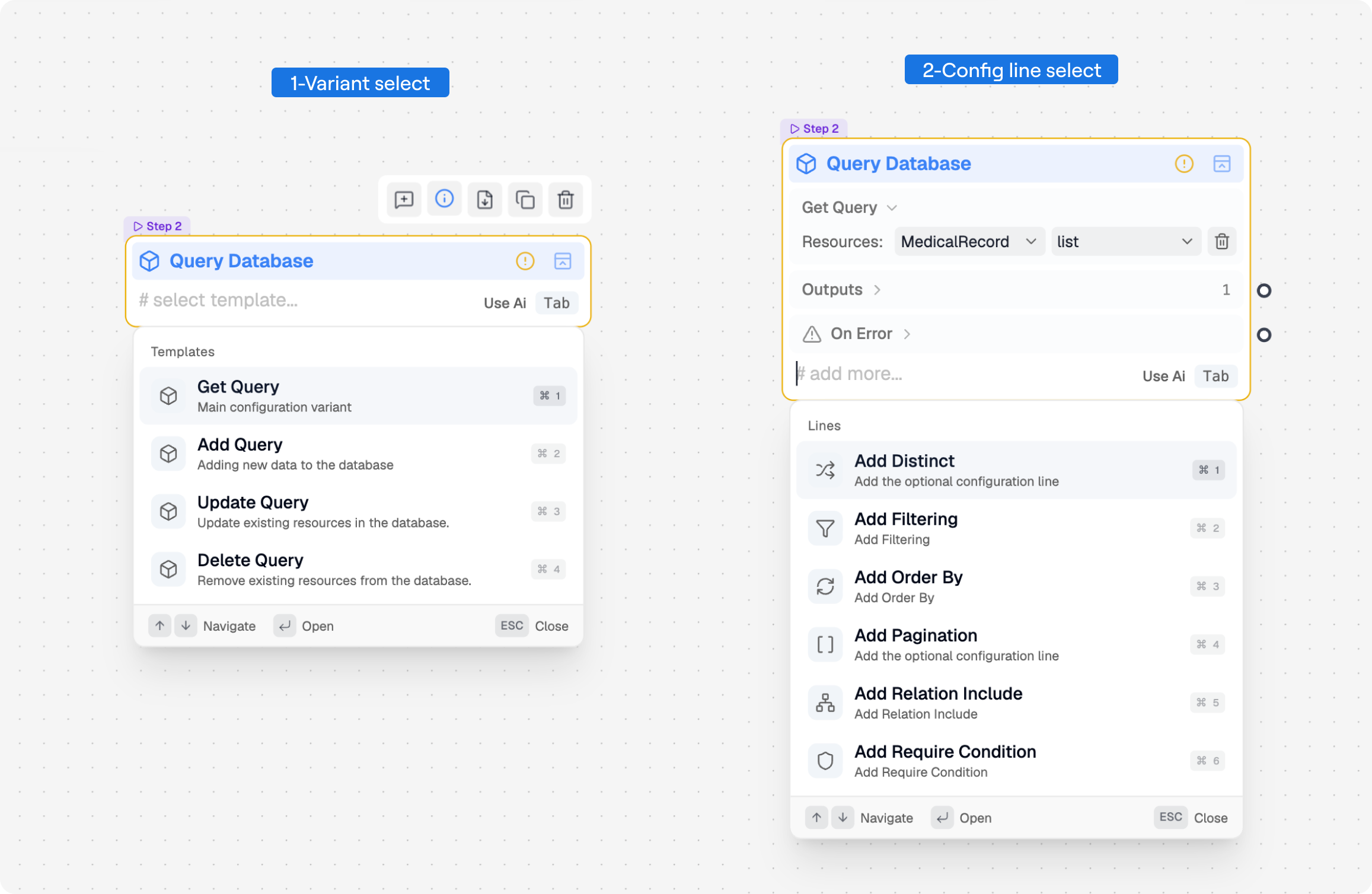
Variants
A variant is an operating mode of an action. For example, a Query node can expose different modes for reading, creating, updating, or deleting data. When creating a reusable node, variants come from the main use cases you define in the logic node structure.
- A node with one variant loads it immediately.
- A node with multiple variants starts with # select template. Choose a variant from the suggestion menu.
- Changing the variant resets values and optional elements that belong to the previous mode. Recheck all connections after switching.
Choose the variant whose outputs and errors match the request outcome. Do not select a variant only because its label is similar; review its required lines and available ports as well. Node creators configure those variant-specific lines and ports in Node Builder variants.
Config Lines
Config lines are the sentence-like controls inside an action node. They define how the action behaves without requiring code. In a custom node, these lines are the settings groups described in Logic Node Overview and configured in Node Builder.
| Line type | Behavior in the flow |
|---|---|
| Required | Appears with the selected variant and must be completed. |
| Optional | Can be added from # add more and removed when no longer needed. |
| Multiple | Can be added repeatedly for rules such as filters or assignments. |
| Generic object | Expands from a selected entity into fields based on that entity's attributes and relationships. |
Use the input plate to add optional lines, additional instances, optional inputs or outputs, branch flows, and error handles supported by the active variant. These options are controlled by the custom node's element packs, instances, conditions, and behaviors.
Fields
Fields are the individual controls inside a config line. Their appearance depends on their purpose and type. For custom nodes, fields are defined in the visual structure and then mapped into the code template through configuration tags:
- Text labels make the line read like an instruction.
- Typed inputs accept text, numbers, booleans, or dates.
- Select fields choose a fixed option, entity, attribute, or condition.
- Value fields accept a literal, environment value, request input, or connected action output.
Input Tags and Attribute Access
A value-capable field can call an action-node input by inserting an input tag. The tag number follows the input's current position in the node: the first input is {{0}}, the second is {{1}}, and so on. On the canvas, Avora renders the braces as a compact numbered chip.
| Canvas value | Stored tag | Meaning |
|---|---|---|
0 | {{0}} | Use the complete value connected to the first node input. |
1 | {{1}} | Use the complete value connected to the second node input. |
1.hashedPassword | {{1}}.hashedPassword | Read the hashedPassword attribute from the object connected to input 1. |
ENV.API_KEY | {{ENV}}.API_KEY | Read an environment value by key. |
Select a tag-capable field and choose an input from its suggestion list. Press Enter or Tab to insert it. When an input contains a workspace object, type a period after its chip to open the object's available attributes, including inherited attributes. Selecting one produces a tag such as {{1}}.hashedPassword.
By default, a field uses its configured literal or default value. Setting its default mode to Input stores an input tag instead, so the connected runtime value is used automatically. Input tags work in typed input fields and in single select fields that have Custom Input enabled; node creators configure these defaults in Node Builder fields.
Avora compares the complete input tag's declared type with the destination field's type constraint. Compatible numeric types are accepted together, workspace object types can follow their inheritance rules, and any or unresolved dynamic values remain permissive. An attribute tag is resolved from its parent object at runtime; when its exact subtype cannot be determined in advance, confirm that the selected attribute matches what the destination field expects.
The number displayed by a tag comes from the node's input order. Removing an input clears tags that referenced it and shifts later tag indexes. During generation, every remaining input tag must have an inbound edge; an unbound tag cannot be resolved to a runtime value and causes a generation error.
When a field offers workspace objects, choose the entity first so dependent attribute lists can filter correctly. A field with a required type constraint shows a validation issue when the connected value is incompatible.
Prefer connections for values produced elsewhere in the request. Use literal values for stable configuration and environment references for secrets or deployment-specific settings.
Flow Inputs and Outputs
The request contract and its logic flow share the same inputs and outputs. Adding or editing them in one view updates the other.
- In the input group, add any missing request value and set its type.
- Connect the input's output port to the action field that consumes it.
- Add or configure action-node inputs and outputs only when the selected variant allows it.
- Route the last action result to the matching request output.
- Return to the Request Builder to confirm names, types, and status codes.
The complete-flow demo above shows these steps together: creating the contract fields, connecting an input to the action that consumes it, and routing the final value to a request output.
An action input can accept only one active connection. Connecting a new source to the same target replaces the previous edge. Avora checks compatible types while you connect; warnings or errors indicate where the flow contract needs attention. In custom nodes, the available inputs and outputs are defined in element packs.
Connect and Order Actions
Connect from an output handle to the compatible input handle on the next node. The direction of the edge is the direction in which the value becomes available.
Avora uses those input-output connections to infer the action order. A node runs after the values connected to its required inputs are available. In the example below, Find User is Step 1 because it consumes the request input, Verify Password becomes Step 2 because it needs the found user, and Generate Token becomes Step 3 because it needs the verified result and user object.
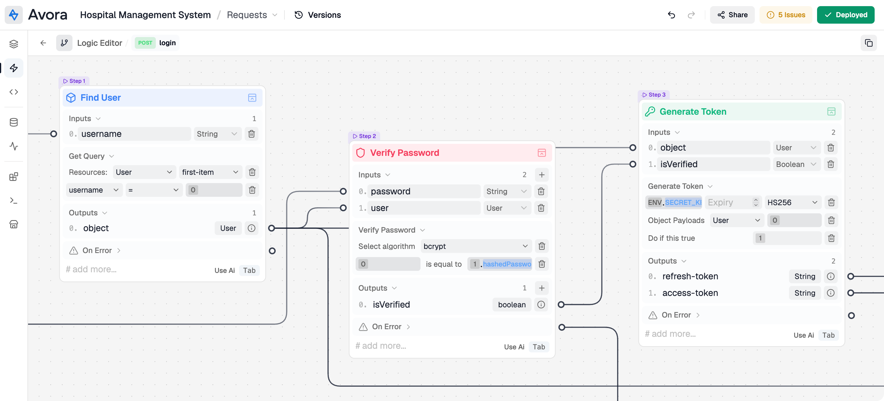
When you reconnect an edge, pass a different output, or add a new required input, the step order can update because the dependency graph has changed. Keep the visual layout aligned with that automatic order:
- Place request inputs at the left.
- Arrange actions in execution order from left to right.
- Keep related branches close to the node that creates them.
- Place request outputs at the right.
- Avoid crossing edges where moving a node can make the data path clearer.
Some nodes expose named nested flows such as If True, If False, or a loop body. Select the named flow to open it, build the actions inside it, and use the breadcrumb to return to the parent. A named flow describes execution; a regular output carries a value. Treat them as different parts of the action contract; custom-node creators define branch handles in Logic Flows.
Before considering the flow complete, trace every request input to its consumer and every possible action outcome to either another action, a nested flow, or a request output.
Error Handling
Action nodes can expose an On Error group with one or more named failures and status codes. Error paths should be deliberate parts of the flow, not unconnected leftovers. For reusable nodes, these failures are part of the node's error handler contract.
- Expand On Error on the action node.
- Read each error message and status to understand when it can occur.
- Add optional error handles from # add more when the variant supports them.
- Connect each relevant error handle to a compatible request error output or to recovery logic.
- Enable Continue Workflow only when later actions are safe and meaningful after that failure.
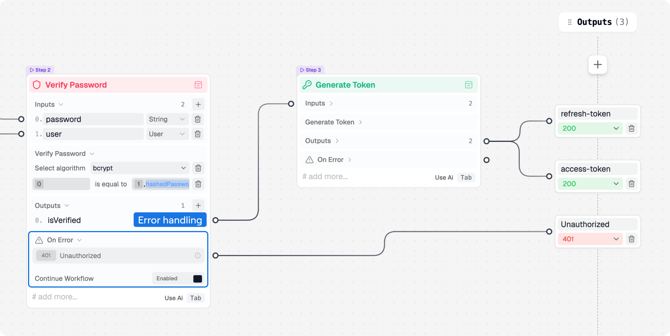
In the figure, Verify Password has two outcomes. Its success output continues to Generate Token, which returns the refresh-token and access-token outputs. Its Unauthorized error output is connected directly to the 401 request output, so that failure can return a clear response without adding another action node.
When Continue Workflow is off, an action error stops the current path unless the error is routed to a request output. When it is enabled, the workflow can continue through the remaining connected logic after that error is handled. Use it only when the downstream nodes can still run correctly; do not let token generation or response mapping depend on a value that the failed action did not produce.
Review the finished flow with these checks:
- Every required config field has a value.
- Connected field types are compatible.
- Every success path reaches an appropriate 2xx output.
- Expected caller errors reach clear 4xx outputs.
- Unexpected service failures use an appropriate 5xx output.
- Nested branches return to a defined outcome.
- No secret is stored as a plain literal when it should come from the environment.
Return to Request Builder to adjust the public request contract, or continue to Code Generation after the workspace passes validation.